Code structure
Overview
Synfig is divided into three components: ETL, synfig-core and synfig-studio.
ETL is a template library that implements reference counting, portable threading and other low-level stuff. Every part of the Synfig project uses ETL in some way. It is like the C++ STL.
synfig-core is Synfig’s backend. It renders scenes and knows how to read and write Synfig XML files. This directory contains the Synfig library and the Synfig command-line tool.
synfig-studio is the graphical editor. It uses the GTK+ widget library. If you want to hack on the interface, this is what you should look at.
The structure of synfig-core is:
synfig-core/src/synfig/- Code of “libsynfig” library. This is actually the main part of synfig-core. It contains code of render engine and routines for reading/writing Synfig’s files. The libsynfig library is used by all other Synfig’s components.synfig-core/src/modules/- Functionality of libsynfig can be extended with modules and this directory is a place for them. A module can do following things:- Add support for importing specific file format(s). Examples:
synfig-core/src/modules/mod_png/mptr_png.cppsynfig-core/src/modules/mod_bmp/mptr_bmp.cpp
- Add support for exporting (rendering) to specific file format(s). Examples:
synfig-core/src/modules/mod_png/trgt_png.cppsynfig-core/src/modules/mod_gif/trgt_gif.cpp
- Implement a layer type(s). Examples:
synfig-core/src/modules/mod_geometry/circle.cpp- Circle Layersynfig-core/src/modules/lyr_freetype/lyr_freetype.cpp- Text Layersynfig-core/src/modules/mod_noise/distort.cpp- Noise Distort Layer
- Implement a valuenode (see below on valuenodes). Example:
synfig-core/src/modules/mod_noise/valuenode_random.cpp
synfig-core/src/tool/- Code of synfig command-line tool (binary is simply calledsynfig). It uses libsynfig to read Synfig files and render them in any supported format.
Main components of synfig-studio:
synfig-studio/src/synfigapp/- Code of libsynfigapp library. This is a layer between GUI and libsynfig (from synfig-core). It contains code for actions - operations that transform loaded Synfig’s file in some way. When user makes some change to Synfig file in GUI, then an action is called that does the actual modification.synfig-studio/src/gui/- Code of GUI written in GTKmm. This defines how application looks and behave.
So, we have following structure:
gui ---> libsynfigapp -------> libsynfig

           synfig-cli -------> libsynfig
synfig-core
Layers
The basic building block in Synfig is Layer.
Note
synfig-core/src/synfig/layer.cpp
Layer either displays some graphical information on the screen (circle, line, text, etc.) or does some transformation of graphic information under it - i.e. acts as filter (blur, translation, noise distortion, etc.).
Note
- Built-in layers:
synfig-core/src/synfig/layers/
- Layers as modules:
synfig-core/src/modules/lyr_stdsynfig-core/src/modules/lyr_freetypesynfig-core/src/modules/mod_examplesynfig-core/src/modules/mod_geometrysynfig-core/src/modules/mod_gradientsynfig-core/src/modules/mod_noisesynfig-core/src/modules/mod_particle
Layers are placed in particular order.
- Layer 3
- Layer 2
- Layer 1
Layers are rendered from bottom to top.
Context and Blend Methods
All graphics information under particular layer is called its Context.
In example above Layer 2 together with Layer 1 are context of Layer 3.
If Layer 3 is a graphic layer, then it displays some graphic information, which is composed with its context (Layer 1 and Layer 2). The way how Layer 3 composed with its context is defined by layer’s Blend Method.
Note
synfig-core/src/synfig/color/
TODO: Add link to list of available blend methods
If Layer 3 is a filter layer, then it transforms graphic information created by Layer 1 and Layer 2.
Canvas
A structure which stores a list of layers is called Canvas.
Note
synfig-core/src/synfig/canvas.cpp
A canvas can also store other canvases. This is how layers organized into hierarchy.
In GUI canvases represented by Groups, but in code they are called Paste Canvases. Paste Canvas is a special type of layers, which holds Canvas of other layers.
Note
synfig-core/src/synfig/layers/layer_pastecanvas.cpp
Every Synfig file has a Root Canvas, which contains all layers. Also it can have several Exported canvases - a separate canvases that are outside of Root Canvas.
Paste Canvas can be inline (i.e. include all its content in itself) or linked (i.e. reference content from exported canvases or other Synfig files).
Note
Loading Synfig file: synfig-core/src/synfig/loadcanvas.cpp
Saving Synfig file: synfig-core/src/synfig/savecanvas.cpp
ValueNodes
Every layer has a set of Parameters, which define how layer is rendered (and what it is rendering).
In simplest case layer parameter can be defined by a value of particular type - ValueBase (Integer, Real, Bool, Color, etc).
Note
synfig-core/src/synfig/base_types.cpp
In complex case parameter can be defined by ValueNode. ValueNode is a formula that produces a value from some calculations. Each ValueNode has parameters that define input data for formula. Parameters of ValueNode can also be represented by ValueBases (static value) or ValueNodes (calculated value), so it is possible to construct nested formulas.
Note
synfig-core/src/synfig/valuenodes/
synfig-core/src/modules/mod_noise/valuenode_random.cpp
It is possible to link ValueNodes and ValueBases among different parameters (and among different layers).
I.e. for two circle layers A and B we can link their Radius parameters (both static values, ValueBase). In this case, changing radius of one circle will change radius of another (see https://wiki.synfig.org/Doc:Getting_Started#Linking).
In more complex case we can have Radius parameter of circle A defined by Scale ValueNode. The Scale ValueNode have two parameters - “Link” and “Scalar”. If “scalar” parameter is set to static value 2.0 and “Link” parameter is linked to “Radius” value of circle B, then circle A will always have a radius twice bigger than circle B.
TODO: Make an illustration of layers sharing same ValueNodes/ValueBases
Among all different ValueNodes there is a special ValueNode, which deserves a special attention - it is called “Animated”.
Note
synfig-core/src/synfig/valuenodes/valuenode_animated.cpp
synfig-core/src/synfig/valuenodes/valuenode_animated.h
synfig-core/src/synfig/valuenodes/valuenode_animatedinterface.cpp
synfig-core/src/synfig/valuenodes/valuenode_animatedinterface.h
This ValueNode stores multiple values of parameter for different moments of time and calculates interpolated values between them.
Rendering process
When Synfig needs to render a frame it starts by evaluating parameters of layers. If a parameter is ValueNode (calculated value), then it evaluates its parameters. This process works recursively, going all the way down to the leaf nodes, calculating their value, then calculating the value of their parent, and so on until reaching the root of the node tree.
Since ValueNodes can be animated (meaning that they can change value at different points of time), so the entire tree needs to be evaluated on each frame.
Once a layer has the values for it’s parameters, it renders the intended shape or effect onto a raster. A raster is an array of pixels, each pixel with its color/opacity. It doesn’t carry any information about the vector shapes that it’s representing, only their pixel data.
Then comes blending. The raster result of the previous layers is combined with the current one according to the set blending method. Some layers (transforms, distortions, etc) just modify the raster result of the previous layers and pass that on to the next layer, instead of blending.
Note that a layer sees all the layers underneath as a single combined raster. That layer cannot distinguish the pixel data that comes from the next layer that’s underneath, from pixel data from any other layer that’s underneath.
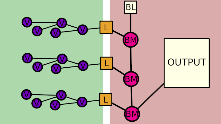
On diagram: “V” stands for ValueNodes, “L” for layers, “BL” for blank layer (completely transparent layer default background), “BM” for blend method.
Render engine
Now, let’s talk about render engines.
In fact there are two of them now.
The new one (called “Cobra”) is the our latest development and it is the future of Synfig.
And there is an old one (without a name). As of version 1.2.0 it is deactivated. But some layers are still use its code, in case if they are not ported to Cobra yet (Synfig fallbacks to old render engine). This generally works much slower comparing to case when layer’s code is ported to Cobra.
If you examine code of any layer, you will see a function called accelerated_render() - this is a code of old render engine.
Old rendering engine examines stack of layers in two passes.
First, it is going from top to bottom and applies required transformations (when possible). Also, it defines required context for rendering each layer. On second pass it goes from bottom to top. It is doing actual rendering for each layer and mixing it according to Blend Method with previous layers (context).
I.e., if we have Stretch Layer on top of Shape Layer, then on first pass Synfig goes down and applies stretch to all vertices of Shape Layer, thus eliminating Stretch from operations. Then on rendering stage it renders Shape Layer only (as stretch is already applied on first pass).
On the other hand, if we have Blur Layer between Stretch Layer and Shape Layer, then it is not possible to apply Stretch (because Blur is a raster-based effect). So it doesn’t eliminates Stretch on first pass. On second pass it renders all 3 layers - Shape, then blurs it and finally stretches result.
Now, let’s talk about Cobra engine, which is more advanced.
Note
The code of Cobra render engine is located in /synfig-core/src/synfig/rendering
Its main concepts are: Task, Queue, Optimizer, Sub-Engine and Renderer.
Task is the main primitive of Cobra render engine that does something. This is like Layer in Synfig’s concept, but even more simple/low-level. I.e. there is a task for blending, task for drawing filled region, task for affine transformation, etc.
For example, Outline and Region Layers are executed by the same task - the one that drawing filled region (Task Contour).
Note
synfig-core/src/synfig/rendering/common/task/
synfig-core/src/synfig/rendering/software/task/
synfig-core/src/synfig/rendering/opengl/task/
So, why we need both Tasks and Layers? How do both concepts relate to each other? Layers are good for user (they help to construct and organize animation document) and Tasks are good for render engine (they are not good for editing, but allow to render animation document as fast as possible). Tasks describe user’s animation document in a low-level form, in a language that is suitable for render engine.
In a very simple view Cobra render engine also works in two passes. In first pass it takes a tree of Layers, and constructs a Queue of Tasks. In second pass it executes tasks in Queue (does rendering).
Note
synfig-core/src/synfig/rendering/renderqueue.cpp
Queue is a linear list, but Tasks can have dependencies. I.e. task A can depend on task B and C. That means when render engine processes Queue, it skips task A unless tasks B and C are ready. The task A is executed in next pass, after B and C are done. This allows to organize parallel (multi-threaded) rendering.
When Cobra does its first pass (transforms Layers to Queue of Tasks) it applies Optimizers.
Optimizers are analyzing list of tasks and re-organizing it to speedup rendering process.
Note
synfig-core/src/synfig/rendering/common/optimizer/
For example, there is an optimizer that looks for a sequences of Region/Outline Layers which could be merged into one task and thus rendered in single pass (without intermediate blending functions).
Now let’s get to Sub-Engines.
It is clear there is a possibility to implement one particular task in different ways. For example, we can draw a vector region using straight-forward CPU calculations (software method), or activate OpenGL and use its functions to draw the same shape using videocard (hardware-accelerated).
In the same fashion, we can do Gaussian blur operation with straight-forward CPU calculations, or utilize hardware-accelerated methods.
So, all tasks are grouped by implementation method, forming a Sub-Engines.
Currently we have 2 sub-engines - “software” (the main one, all tasks done with calculations on CPU) and “OpenGL” (all tasks are hardware-accelerated using OpenGL, it is currently broken).
Software Sub-Engine -
`synfig-core/src/synfig/rendering/software/`Tasks of Software Sub-Engine -
`synfig-core/src/synfig/rendering/software/task/`OpenGL Sub-Engine -
`synfig-core/src/synfig/rendering/opengl/`Tasks of OpenGL Sub-Engine -
`synfig-core/src/synfig/rendering/opengl/task/
Generally, it is possible one Sub-Engine can use tasks from other Sub-Engine. I.e., when OpenGL Sub-Engine is active and there is some task missing, then it can be replaced by task from Software Sub-Engine.
Each Sub-Engine can have several configurations with different set of Optimizers. We call those configurations Renderers - and this is what user actually see when choosing renderer via “Edit” -> “Preferences…” -> “Render”.
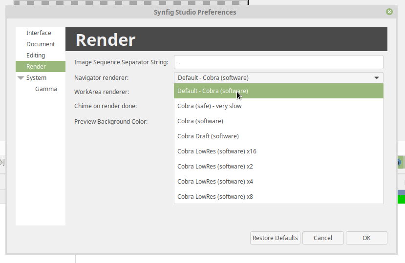
For example, “Draft” and “LowRes” rendering modes are just Renderers of Software Sub-Engine.
Note
Default Software Renderer -
synfig-core/src/synfig/rendering/software/renderersw.cppSafe-mode Software Renderer (not uses Optimizers) -
synfig-core/src/synfig/rendering/software/renderersafe.cppDraft Software Renderer -
synfig-core/src/synfig/rendering/software/rendererdraftsw.cppLowRes Software Renderer -
synfig-core/src/synfig/rendering/software/rendererlowressw.cpp
Now, let’s get back to Layers.
We already know how Layers define their rendering for old render engine. But how this done for Cobra render engine?
If layer is ported to Cobra engine, then you will see build_rendering_task_vfunc() or build_composite_task_vfunc() or build_composite_fork_task_vfunc() functions. So, in Cobra engine layers just use tasks as building blocks to construct structures which produce required output.